

 I’m continuing to work on the 3rd installment of the EMC2 and Servo tutorial, but I realized that I hadn’t seen any great treatments out there for simple e-stop implementations with EMC2 or otherwise in the hobby CNC realms. This is the solution I’ll be using as part of the tutorial apparatus.
Safety systems aren’t sexy and so from what I’ve seen in the community those who know what they’re doing quietly implement them on their own systems but then the rest of the hobbyists and newbies may not even be aware of the need for such things and in the rush to get a machine running and doing the sexy stuff leave themselves open to more risk than is strictly necessary.
Robin Carver over at www.hs-compliance.com has an excellent overview of emergency stop circuits and their use in “The Emergency Stop – the button of last resort” (PDF).
Doug Nix also contributes some additional understanding at machinerysafety101.com in his nine-part series.
When I’ve designed, built and maintained industrial machinery it was always an extra expense and effort to include appropriate safety measures including guarding and one or more e-stop circuits. However it’s one area where nobody in industry argues about the necessity. If they do, they don’t tend to last very long. Darwin at his best!
As hobbyists it’s often a neglected area as we just want to see things move and work and we often elect to leave pieces like safety devices until later. There’s often the conception that if we’re wearing our safety goggles then we’re doing the responsible thing and that’s that.
We can be doing more to protect ourselves while chips fly, dust scatters and lasers fire.
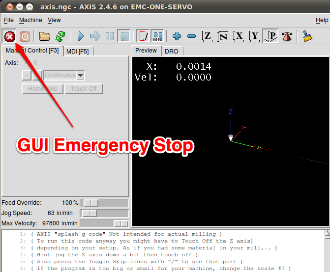
EMC2 has a nice little e-stop button on the screen that will trigger a halt to the machine assuming that the GUI is working properly. The kind software coders even made it so thebutton acts the same as the e-stop button on the screen. Glue a mushroom cap dome on to the key and you’ve got yourself a crude e-stop, but that’s not good enough if somehow the keyboard has come unplugged, or the cord got cut by a machine gone awry. When’s the last time you saw a keyboard cable that was latched in and armored?
Clearly software and even hardware buttons that rely on the PC to operate are not at all satisfactory and I would suggest that by themselves they are even more dangerous due to the sense of false security they can grant the operator.
So what’s left?
Well, the solution that’s followed in industry is to create an “E-Stop Circuit” that functions in hardware and by design triggers the dissipation or containment of dangerous energies so as to stop motion and bring the machine to a halt in the safest way possible. As shown in Robin’s overview there are five “Categories” of system, each with an increasing level of reliability and self-test.
I won’t go into all five categories here. I think Robin does a reasonable job of explaining the differences. Along with the increased levels of safety implied by each higher category is an increase in complexity. For our purposes the higher levels are probably overkill.
Implementing a basic e-stop system is easy enough that it really should be seriously considered for most computer controlled machines in the home shop as well as many of the non-computer controlled ones that have been cobbled together by avid DIYers. The extra evening of effort is really worth it.
For my own purposes with most light machines I end up using a “Category 1” type circuit.

Basic E-Stop Circuit
In the basic circuit shown above, we’re using a relay and two momentary push-buttons.
Operation is very straight-forward. Pushing the “Power On” button closes the circuit to energize the relay which then closes the relay contacts which then latch the relay in its energized state. It will stay on until either the e-stop button is pushed breaking the circuit, or power is lost to the circuit. Also, it’s designed so that the e-stop button can be located remotely and if the wires that run to it gets broken, then the machine will stop and won’t be restarted.
The circuit is usually powered by the same power source as the device you’re looking to control, though there’s no rule about that and it will depend on your requirements and of course what pieces you may already have in your junk drawer. Of course reducing the number of power supplies in use is always a good idea.
The relay itself I’ve shown is a garden-variety double-pole double-throw (DPDT) relay with an appropriate coil voltage and contact ratings. Just about any other combination of poles in single or double throws can be used as long as you have at least a single normally-open contact.
The buttons are distinctly different. The “Power On” button is a normally-open (NO) momentary contact type meaning that you push the button and its contacts close and when you release the button, they open again.
The “E-Stop” button is a normally-closed (NC) type with a mushroom head. It should be of fairly sturdy and reliable construction, because the last thing you want when you need to hit the button is to worry about breaking it. In this case “hit” is accurate as it’s typical when one decides to push the button it’s often not a well considered action and a proper SLAP is often used.
I would also suggest that when you are actually building a machine that is capable of causing damage to either yourself or it, that you mount the buttons permanently and securely so that they don’t move when you are trying to activate them. This is not only important during day-to-day use, but also when you are first testing the machine’s motions.
E-stop buttons come in a fair variety of types that may be worth looking into. Some are spring-loaded and reset themselves as soon as the operator her hand off of it. Others latch down so that some deliberate action is required to reset it. A pull, twist-and-pull or even key-lock action are all common. These help prevent restarts and also aid in identifying which button was pressed in large systems found in industry. There are even illuminated buttons that can be made to glow or flash to draw attention to the button.
There are of course a few embellishments that can add to the circuit’s usefulness.

E-stop Circuit Optional Additions
As shown above, you can add additional buttons in series in the circuit to enable you better coverage and the ability for the operator or a bystander to more easily reach the buttons while still maintaining a safe distance.
Multiple buttons may seem like overkill in the context of small hobby machines and it often is. However think about the size of your machine and decide if you can safely reach the button from any point where you might be operating or watching the machine.
The second option shown above is an LED indicator. This could also of course be a lamp. This simply tells you at a glance when the machine is enabled. Frequently I use an illuminated push button for the “Power On” and wire it so that it illuminates when the relay is energized so I can immediately tell when I’ve enabled the machine.
That’s all great and all, but back to the topic of EMC2. I really don’t care for the idea of the GUI button. It’s ok for simulation but not real machine use. As mentioned before, the keyboard is also problematic so I prefer to just ignore the fact that either of those exist. What is nice to do though is integrate the e-stop circuit back to EMC2 so that it knows that an e-stop has been triggered and build additional functionality on that (ie. turn off coolant pumps, etc.)

EMC2 Integrated E-Stop Circuit
In the schematic above you can see my final(ish) solution to fulfill our basic needs. The Power Out connects to servo/stepper drivers and could even be used to enable a spindle or other devices.
In this case we’re powering things using a 24VDC power supply as I was already using that to power a servo drive. The servo is powered by the Power Out signal.
The status of the e-stop circuit is passed to EMC2 via a simple voltage divider which converts the 24V signal to 5V and then connects to pin 15 on the parallel port.
While an optically isolated circuit would be safer for the PC (or at least the parallel port), it’s slightly more work to implement so in this case I elected to do the “easy” thing while still making the machine safer for humans. The risk is that if for some reason the 1k resistor were to get disconnected the result would be 24VDC applied directly to the parallel port’s input which may or may not cause damage. I’ve made sure my connections are robust so I don’t think this will be a problem.
Also in the last schematic you’ll notice a new diode placed across the relay coil. This is to prevent the back EMF generated when the coil is turned off from affecting the rest of the circuit including the parallel port. The back EMF could be into the hundreds of volts so obviously we want to avoid that.
Finally now we need to configure EMC2 to look at pin-15 on the parallel port so that it reacts to the circuit appropriately. This is done very simply.
For example, if you have a look at the etch-servo.hal or with stepper_inch’s standard_pinout.hal, all you have to do is find the line:
net estop-loop iocontrol.0.user-enable-out iocontrol.0.emc-enable-in
Then change it to:
net estop-loop parport.0.pin-15-in iocontrol.0.emc-enable-in
Where parport.0.pin-15-in is modified for the appropriate parallel port (in my case it’s port 0, but for you it might be port 1,2,3 etc. if you’re using an expansion card).

Estop Mode Active

EMC2 Powered On
Now if you start EMC2, and then try to click on the GUI e-stop button, nothing will change.
However if you press and release the Power On button to energize the relay, you will see the buttons change their appearance to indicate that EMC2 has changed from being “In E-stop” to “Power On” modes.
Hit the E-Stop button and if all is working correctly, you’ll see it change back!
We’re one step closer to being able to get things moving safely.
As a final note, here’s a parting image of what my implementation looks like just to show that it doesn’t have to add much to the overall build. You can see the single relay, terminal blocks where the connections are all made, and buttons. Hard to see/hidden in there (with the terminal blocks) are the additional diodes, resistors and the power-on signal that’s running out to the parallel port breakout card.

My E-Stop Buttons & Relay
Now on to the fun sexy stuff!!!
![]()